Saturday, December 6, 2014

Making a Plan and Leashing Ambition

Putting the Leash On Ambition…

When I planned on making this #Lightsaber to join the Rebel Legion, I didn't realize how ambitious that idea was at the time.  As I worked through various decorative techniques, it still didn't occur to me that this would really challenge my skills.  However, as I look at the number of connections I wanted to make, I see how it can get very overwhelming planning how to put it together.  So, I plan to take out the more ambitious parts of the saber: mainly the crystal chamber.  While that only removes 4 wire connections, it removes the most difficult solder joint on the Petit Crouton sound board - on a joint between 2 surface mount components.  That also saves determining the resistances for the multi-color LED to light the crystal.

Also, by removing the crystal chamber, I don't have to figure out how to route the wires from one end to the other in a pleasing way.  That gives me more room to place the more vital components; like the Li-ion battery, the Petit Crouton, the Color Extender, and the speaker.  Essentially, removing the crystal chamber makes the saber less cramped.

Making a Plan…

While I've been recovering from a cold, I took some time to look at how to arrange the contents of my saber.  The basic components for this saber are (in no particular order) a battery, a sound board, a speaker (to play from the sound board), an LED (suitably high powered), 2 switches (one momentary, one latching), and a recharge port.  While you can vary some components, those are the basics for a running saber that can be used and looks "real."

In my saber, I'm adding the Color Extender board and changing the latching switch to a momentary switch.  The Color Extender allows up to 3 LED dice to be mixed for color and Flash-On-Clash response (don't worry, I'll demonstrate these when I video my working saber). 

Anyway, as you can guess, there's a lot of planning as to how to arrange all these parts.  Below is a picture of the parts laying beside the my basic saber body.


From left to right, the speaker in a housing, the battery with the Petit Crouton and Color Extender boards, the recharge port, and 2 momentary switches.  Now, the boards get attached to the battery in the order they've been set, with the Petit Crouton as close to the pommel end of the saber as possible.  Here's a closer picture of the group.


The battery is a little over 5 inches in length and the boards will easily fit in the saber once attached to the battery pack.  Before I do that (in a later blog), I want to make some solder connections (also a later blog, sorry).  For now, I'm placing the parts so that I can visualize what needs to be done to place them in the saber.  For instance, if you notice the boards a fairly exposed electrically and could short to the aluminum saber body.  That means I need to come up with a method of isolating the battery and boards from the aluminum.  Rob Petkau of Genesis Custom Sabers uses PVC inside the saber body and that sounds like the best way to do it to me.  That adds to my build list, if I can't buy it, a piece of PVC pipe fitted inside the saber.

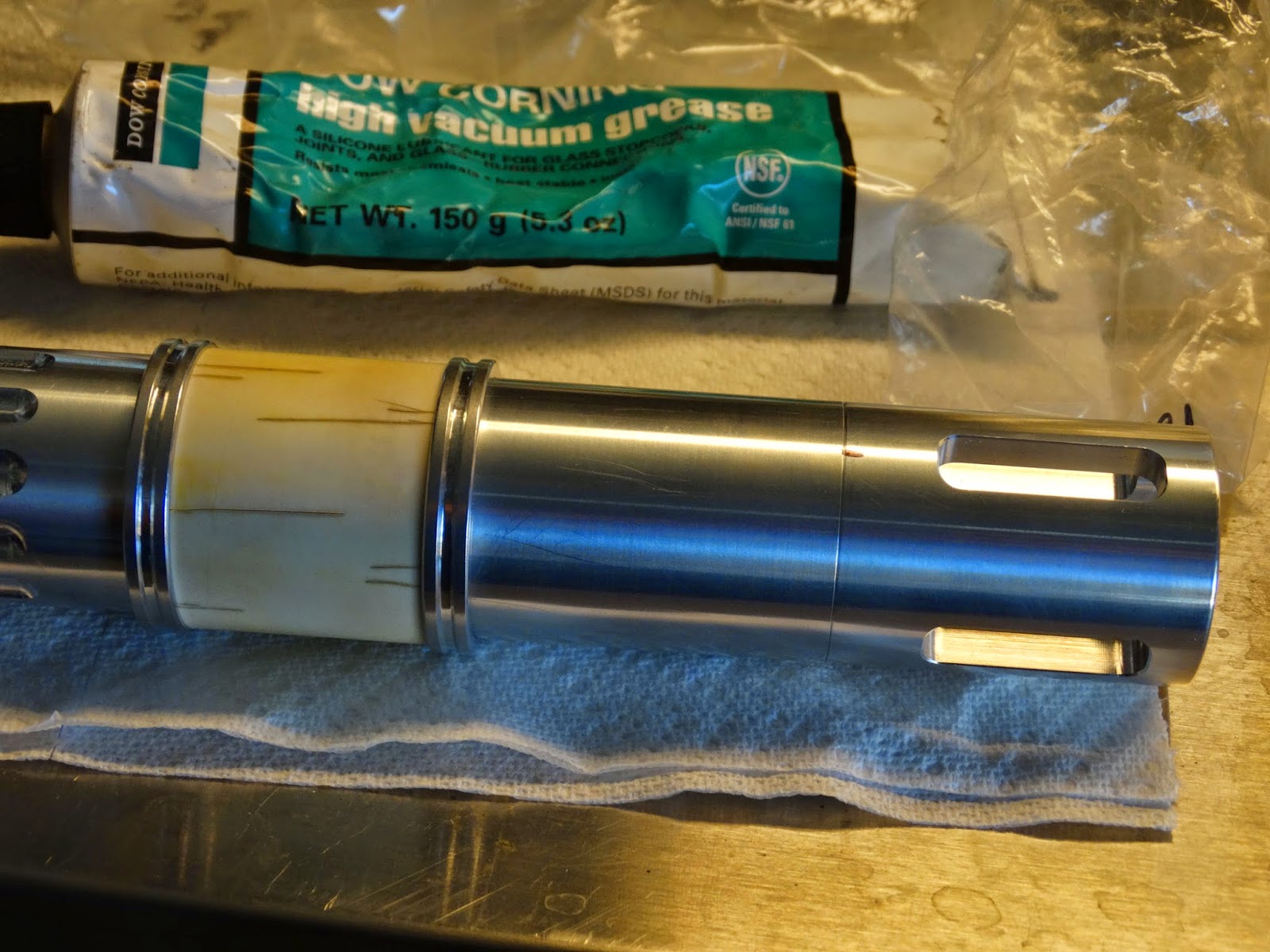
Another thing to note for the PVC insulating piece, it may need to have an opening in the side to insert the battery and board grouping as, I think, I didn't attach enough length of wire to the LED unit in the saber emitter - as seen in this pic.


Since the wires only reach about 2 inches from the rear of the saber, it may not be enough length to have the batter clear of the saber body when I make the solder joints.

Now, on to the switch and recharge group.


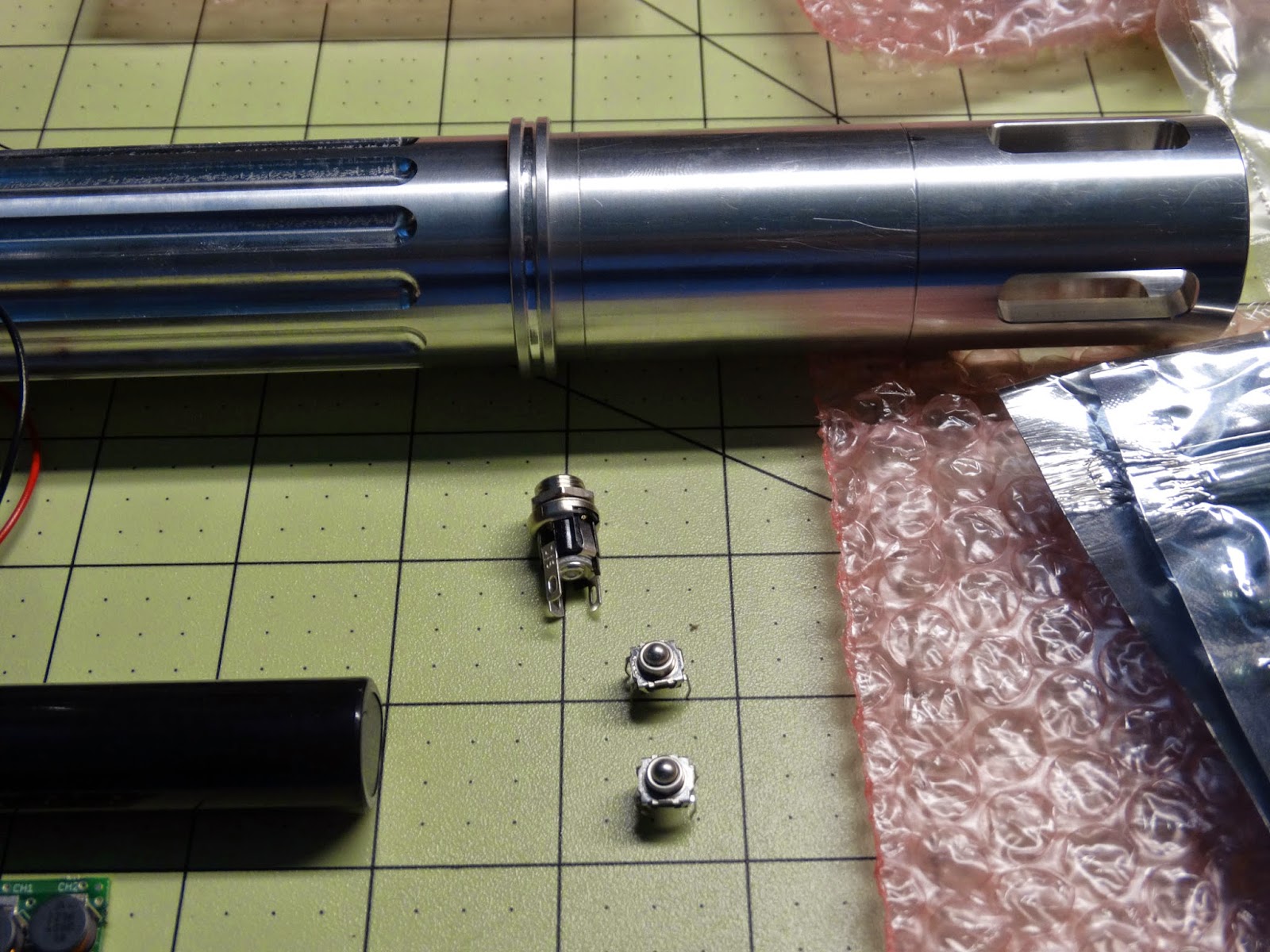
Originally, I planned on the recharge port being at the pommel end of the saber but I decided to move it up with the switches.  That will place it where I can see whether the "kill" key is in the switch or not before I try to turn on the saber.  The "kill" key is a piece of plastic that, when inserted in the recharge port, "kills" the power to the sound board because it engages a switch in the plug - more on that in a later blog entry.

The two momentary switches will be placed so that the switch on the right (when the saber's "dangerous" emitter end is pointed away from the user) will activate the saber and the button on the left will switch the auxiliary controls (blaster/clash effects, lock-up effect, and switching sound banks).  Keeping with canon #StarWars, the switches will look identical in the final saber. 

To mount the switches, I got this piece from The Custom Saber Shop to hold them.


The switches don't quite fit this device which was expected: it was designed for different switches.  It, however, helps me visualize how they will sit on the saber and gives me options for the recharge port.  The recharge port can be placed ahead (towards the emitter) of the switches or, more likely, behind the switches and toward the pommel/hilt end of the saber. 

Why place the recharge port toward the pommel/hilt end?  It's a small difference to the layout of the saber but the "kill" key will stick out of the saber and feel awkward while in the saber.  If I go to activate the saber and feel the "kill" key lump under my fingers, that will remind me to remove the "kill" key so I can use the saber.  If the recharge port is ahead of the switches, then I might miss that the saber isn't "ready" to use.  As I said, it's a small change in the layout of the saber, but it makes a huge difference to the user to have a reminder if the saber is ready or not.

It also helps to design the PVC insulator so that I can mount the recharge port.  I may even design the insulator to also hold the switches.  That way, the internal components will move as a unit as the saber is used.

Planning the layout of the internal components makes it easier to make other decisions on the fly while building. 

What's Next?

Well, I know that there are some parts to make.  I need the PVC insulator before I do any soldering: it serves as my layout.  I plan to put a shroud on my saber, so that's a must.  I'd also like to make a custom emitter safety plug for the saber.  And I still think some fake bone would be cool on the saber, so I'll shelf that one.

At this point, there are jobs that have to be done in order and a few that can be built in any order separately.  To make the emitter plug, I have to drill and tap a blade retention screw in the emitter.  Building the shroud meshes well with drilling and tapping the blade retention screw.  Also, the blade retention screw is kind of like the center-line of the saber; everything is based on it's placement.

That means, the next blog will be about drilling and tapping the blade retention screw and making a shroud for my saber. 

I hope you've enjoyed today's entry.  You can follow me on Twitter @jek_creations & please feel free to tell me what you think about the blog.

Saturday, November 22, 2014

Evolution of the Saber

Lightsaber Evolution

Taking a look at the parts of my saber and my current thoughts on it, I'm making a much simpler design than I first envisioned.  Below is a picture of my first concept for the lightsaber I am building.


The above saber came in at over 15 inches in length.  Compared to those seen in the movies, that's a massive saber - a double blade model should be that long.  So, I took out the choke and came up with my Mark II, pictured below.


Removing the choke brought the saber down by 2 inches for an overall length of 13 inches.  This model keeps the crystal chamber, but it is still a little on the long side for me.  The other issue is that wiring a crystal chamber on the Petit Crouton sound board requires relatively simple welds, but one is a very small weld.  The danger with this small weld is that I'm not that confident with my soldering skills (yet) to try that weld on my only board.  So, I've moved on to the Mark III model below.


Mark III has no crystal chamber.  I will design and build one, but I won't add it to the saber just yet.  Instead, this saber will have a compressible emitter plug to sit in place of the blade when not being used - it'll act as protection for the eyes when activated without a blade.  I was planning to add a blade shroud from the beginning and, now that Mark III is just over 10 inches, the shroud will not add too much in length to the saber.

Conceptualizing the Compression Plug

The compression plug is a bit of decoration for the blade when not in use.  When closed and secured in the emitter end of the saber, it will protect a users eyes from the light of the activated LED unit.  When unlocked, the compression plug expands to expose a core - this can be a crystal, or a plastic core that dissipates the light of the LED.  Basically, it's a neat safety device.

Taking some time this week, I sat down with the saber and a engineering pad, and drew up a design for the plug.  Below, you can see the rough design I came up with at the time.


While it looks big on paper, the truth is that this plug will be no more than 2 inches long and 1 inch in diameter.  To keep the compression plug from coming apart, it needs to be bolted together.  That leaves a minimum of 2 bolts to hold it and, probably, no more than 4 bolts.  More bolts can be used, but there is very little room for bolts to take up space in the plug.  I'm leaning, at this time, to make it work with a 3 bolt system.  I think 3 bolts in a triangular pattern holding the plug together will look more exotic.


Here's the picture of measuring the depth of the emitter.  I'm not sure you can read it, but the caliper reads 1.83 inches, which is 17/100 of an inch shorter than 2 inches.  I took another measurement that said that the distance from the end of the emitter to the opening of the 4 windows on the emitter is roughly 3/10 of an inch.  That means I want to make a plug that is more than 1.5 inches long when compressed and not much longer than 1.7 inches in length.  A plug 1.6 inches in length can have a core that is probably 1.25 inches long.  The big factor in the size of the core is the compression of the springs I'll be using in the plug.  I won't know the size of the springs until I've put the entire plug together.

I do know one thing, though: I'm probably not building a core out of Nylon.  Unless the core is very simple, Nylon is not going to be very useful in the core.  As you can see from the picture below, Nylon doesn't have a clean cut off when machined in the lathe.


Hopefully, by next week's blog, I will have machined both PEI and Acrylic so I know exactly which I'm going to use.

Feel free to send me your thoughts on this design.  Follow me on Twitter @jek_creations.

Saturday, November 15, 2014

A Busy, Slow Week

Lathe in use…

Well, another slow week on the saber build.  The lathe has been busy with a piece of mystery metal that I brought back this summer.  The metal is non-metallic, gives off a kind of green corrosion, and is really heavy.  It could be stainless steel (but green is wrong for it's corrosion) or it could be monel.  At any rate, it has finally come off the lathe today.  After the lathe gets a thorough cleaning (remove all metal chips and old grease), is re-oiled and put back together, I'll be back to working the saber.  Here's what the lathe has looked like for the past week or two.


This piece of metal is heavy and, worse, slick.  It's heavy because it's a solid metal cylinder about 4.5 inches in diameter by about 6 or 7 inches in height.  I haven't measured it exactly because machining it isn't a precision (read to tolerance) job.  It was a somewhat ugly lump of metal that is now a shiny uniform piece of metal.

Concepts for the Saber

I'm thinking of modifying the saber so that it doesn't have the crystal chamber.  In part, adding the crystal chamber is cool, but the drawback to it is that I have to solder a very small solder join on the Petit Crouton sound board.  If I mess it up, I have to buy a new sound board, which is not cheap, so I may not add it to the saber.  I am, however, going to go ahead and build the crystal chamber because I may get brave enough and I'd have most of the work done.  So, in the next few weeks, I'll detail the work involved in making the chamber.

Whether I make the crystal chamber or not, I am making something cool to add to the saber: an emitter plug.  The concept is based on some work Rob Petkau did and showed in this video: Compressor Blade Plug.  First off, I can not stress how much I love Rob's work: Genesis Custom Sabers (his saber shop) is top notch from my point of view.  Anyway, when I saw that video, I knew I had to make one for my saber.  The good thing is that it can be used in place of the crystal chamber.

The key, I think, is in sourcing the right plastic.  Plastics have different uses and different qualities because of they are manufactured for those uses.  While sourcing plastic for this part, I'm looking mainly at the light transmission qualities and durability.  While there are very few plastics that are both brittle and translucent in the given size that may be needed, there are a few.  One such plastic is acrylic.  It is clear and easily machinable, but it can "explode" if not carefully machined - it shatters due to it's brittleness under stress.  I currently have to order some acrylic in the right size if I plan to use it in this project.

Two other plastics that I have and will work for this job are PEI and Nylon.  Here they are:


PEI (on the left) is a plastic that is used in relatively high temperature uses: I've heard that the stuff can survive a medical autoclave.  It is amber in color - I call that a German stout amber.  It is easily machined and, in my experience, very durable.  Aside from it's amber color and price, it is ideal for use near an LED that I've heard can melt hot glue.  Using a powerful LED similar to the LED in the saber, here's a picture of it's light transmission.


The other plastic (and the one used by Rob in his video) is Nylon.  We're all fairly familiar with Nylon.  It's major problem is that it is a little devil to machine.  The surface gets ugly when machined or, at least, the last time I machined it, I couldn't get it pretty to save my life.  I'm older and wiser now, and I like to think that I've learned some tricks over that time, so I'm going to give Nylon another go.  As you can see, it transmits light nicely.


Once I've completely serviced the lathe, I'll get some real work pictures up for you guys to enjoy.

Please, send me some comments or questions about anything you've seen done here.  Thank you for taking the time to read.

Twitter: jek_creations

Saturday, November 8, 2014

Just a Small Job

Speaking of Speakers…

Despite having an extremely busy week, I was able to do a very small amount of work on my saber.  All I could get done was soldering the speaker.


Basically, all you need to wire up a speaker is wire, a speaker, a soldering iron, some solder, and some de-soldering braid (or a wire to perform the same function).  I generally use 2 colors of wire so that I can separate "positive" from "negative"; speakers work wired either way, but the board you connect to usually polarizes the speaker.  All "negative" and "positive" mean for a speaker is the flow of electricity and, generally unless marked, speakers don't have a polarity.  The speaker, in this case, is a 2watt speaker with a 28 millimeter diameter speaker.  The soldering iron is up to you for brand and type - I use a Weller with an adjustable power and a very narrow soldering tip (more on that when I solder the sound board).  It's important that you use a rosin core solder - usually 60/40 is what you find.  I include de-soldering braid because it helps fix small soldering mistakes - like turning wires around, etc.


It's a simple matter to solder the wires to the speaker.  On this speaker, there are 2 pads - one wire goes on one side as above and one wire…


…goes on the other side.  Perhaps, this isn't the best arrangement for the wires.  Since the speaker goes into a plastic casement inside the saber, it would probably be better to de-solder these wires from the speaker and turn them so that the wires pass over the center.

Now, to stress why this is the only work I've done on the saber this week.  First, it only just occurred to me that I wired the wires facing the "wrong" way.  Second, and more importantly, I hooked them up to my multimeter and tested for continuity, expecting them not to have continuity.  Anyone who knows about speakers knows that they are an electromagnet driven part (well, I knew that) and that an electromagnet works only by being a continuous stream of current, i.e. it has continuity.  Worried that I wired the speaker wrong or something, I de-soldered the wires and checked the pads for continuity.  They had continuity.  Suddenly, I remembered how a speaker works and could just kick myself for panicking over a properly functioning part.  I decided that I couldn't be trusted to work on the saber anymore this week (especially now that I've tripped or lost my balance twice around critical work in the shop and I just don't do that).

Having realized that I should wire the speaker slightly differently, the next two pictures are kind of funny.


Yep, that's the speaker encased in it's casement.  It's not impossible to remove from the casement, just a pain because I have to remove the speaker without damaging it.  This is how it goes together, though, which is what I wanted to show.  To make the speaker function out of the saber, I'm going to get some craft felt, snip an "X" in it, run the wires through it, and glue it to the back of the casement.

Needing rest…

I'm hoping that I can get more work done on the saber soon.  At the moment, I think I'm in need of some proper rest.  Lately, I'm making too many mistakes and taking too many missteps.  I'm not comfortable especially with tripping over things in a shop - there are power tools like table saws and things to run into and that's not an injury to get.

Tweeting on Twitter

I just joined some to the modern world recently - I joined Twitter.  If you'd like to follow me there, I'm jek_creations - all like that. 

Sunday, November 2, 2014

Light on the Subject

Completed LED Wiring


Okay.  Sorry there are no pictures of the wiring process.  I wired the blade LED unit more on a spur of the moment kind of thing.  Basically, I needed a measurement for an emitter plug and decided that I might as well wire the LED while I was at it.  There would be pictures, but I didn't take the camera out with me that day, so you guys only get the finished product.

The LED is wired with each color die being independently wired rather than being in parallel or series.  This gives me the ability to take advantage of an additional color mixing board rather than one board running (essentially) one channel.

Anyway, here's what the LED unit looks like all set up to be put in the saber.


The unit is encapsulated in an aluminum cover (the gray part) that holds the focus crystal in front of the LED dies and a copper heat sink back that screws into the aluminum cover.  It's a sandwich: aluminum, then focus crystal, then LED board, then thermal tape (to allow thermal transfer to the copper), then the copper.  You may notice that the wires are paired and twisted.


I twist and pair wires when I wire a DC circuit.  To me, it keeps the wires tidy and makes sure that they go to the right places when wired to boards.

The part I'm sure you're interested in more than my wiring technique is whether they light up and what they look like.  Well, until I get the entire unit wired, you'll have to make due with pictures taken running off the diode test on my multimeter.  I'm pretty sure it's test mode is significantly dimmer than they will be wired as a unit.

Here's red.  Note that the multimeter actually says a voltage of 1.679.


Here's the green die.  The multimeter registers the voltage for it and the blue in the overload position - I guess they really want more power.


And finally blue.


Where to next?

From here, I have a bit more to do.  First, the measurement I took after making the LED unit is to make a safety plug for the emitter so that no one gets blinded by an accidental turn on of the saber.  The rumor is that these are close to Class 2 lasers when lit and I'm kinda attached to seeing things.

I'm also making a shroud for the saber.  There's also a whole process for making it look weathered.  The crystal chamber needs to be built and fleshed out.  All the internal wiring needs to be drawn up and wired and arranged in the saber.  I'm making a insulator for the internals so they won't short to the body.  And then, I'll probably have a complete saber.  At which point, I am thinking of making my first youtube video introducing my saber - we'll see (I don't really like how I sound on video :P).

Friday, October 24, 2014

Fixing Mistakes…

So, it's measure twice?

As I owned up to in my previous post, I made my previous fake bone cover just a bit too big.  I did measure twice, but I did also make a mistake.  I measured the piece I'm covering based on the previous version.  In the previous version, I didn't have pieces that "fenced" the fake bone piece in place.  While it is obvious that I should have accounted for them, I took a short cut and used the physical dimensions of the piece rather than putting the whole thing together and taking the measurements.  It was an obvious mistake.


 The above is the new configuration.  The fences surround the crystal chamber - they'll keep the fake bone piece from sliding up and down the saber when finished.


Now, I measure again.  The space is 1.3495 inches.  While the crystal chamber part is 1.5 inches on the face, the "fences" remove some of the space.  It is interesting to know, that 1.3495 is still slightly too big.  If I made my replacement part using this measurement, the fake bone would jam against the "fences" and won't turn.  So, falling back on the rusty wheels of my experience machining parts, I take a guess that the fake bone piece should be cut to 1.3485 inches (or exactly 1/1000 of an inch shorter).  Using the same process as I did in my previous post (so as not to bore you repeating it), I made three new pieces.


They all fit.  Yay!  I took this picture to show how the part looks without making it look like bone.  The picture below shows a closer look at this particular part.


Taking only one of these parts, I go through the process of making the PVC fake bone look more like real bone.  Using an X-acto knife and three colors of paint (along with the liberal use of paint thinner), I have a fake bone on the saber.


As you can see, the fake bone part is in place.  This is actually the third and thinnest walled part because I am really looking forward to taking advantage of the translucence of the PVC when I can finally put the electronics into the saber.  I haven't cut the part to view the window in the aluminum underneath. 
As you can see, I placed a dot on what may be the "top" of the saber.  The dotted window actually  corresponds with a window on the crystal chamber.  Before I cut the window, I want to figure out the size so that I cut it right (I'd like to keep the other two parts on the bench in case I mess up again).

The Tube of Lube…

In the picture above, there is a tube of Dow Corning High Vacuum grease.  That's not there for show or scale; it's there because that's the grease I tend to use in my projects.  In this project, the parts are aluminum and are subject to "welding" when fitted together (although, it's more problematic with stainless steel, in my experience).  This grease is pretty interesting: it's a silicon (or silicone, I switch them sometimes) grease.  It is waterproof, so it won't wash away in water, nor is it subject to degrading due to high humidity.  Anyway, I liberally applied this to the threads of the saber parts before putting them together.  I'll probably apply a few more treatments as I work on the saber.

An insane idea.

In my last post, I expressed an interest in the translucent qualities of the PVC when turned thin for making these fake bone parts.  The idea I had won't seem insane at first blush: I want to try engraving lettering (in a Star Wars font) on the fake bone.  The lettering will look cool when the saber comes on.  Don't believe me, look at this part with a light shining into it to simulate a very bright crystal chamber.


Why is this an insane idea?  Well, engraving lettering on a part is a job for a CNC Machine.  That is, a computer controlled machine turns and carves the part, putting the lettering in as it turns and cuts.  Unfortunately, all I have access to in pure machining power is a lathe, a milling machine, and a few interesting gadgets for them (like a rotary table with dividing plates).  Without a CNC Machine, I can easily cut verticals and horizontals in letters, but diagonals are a very difficult or near impossible task.  I'd have to plunge drill along each letter to a specific depth.  It's messy and extremely time consuming, but possible.  It's simply so time consuming as to be impossible for any practical application.  The challenge is to create lettering in an elegant first pass without extra clean-up afterward.

However, a challenge is just that.  The key to making my idea work is to create a jig that allows me to cut a set of letters based on a stencil.  I've spent the last few weeks since the last post racking my brain on how to do this.  It's obvious to me that I have to have a stencil, a support to hold the part so that I can manipulate it with my hands while the mill spins an engraver, and a guide so that I only cut the marks of the letters and nothing else.  I'm hopeful that I can make this, but it will probably be the most complex jig I'll make in my lifetime.

Friday, October 3, 2014

Faking Bone

Making a Fake Bone Part For a Crystal Chamber Cover

A word on methods:

This is only one method for making a fake bone-like part.  Most people don't have access to a lathe.  It is a convenient tool, but is not a necessity for working up an excellent part.

Making the part:

Above is a picture of my first practice piece (3/4 inch PVC pipe) compared to the actual diameter pipe needed, which is 1 1/4 inches in diameter.  The bigger pipe has been cut much longer than I need for the actual part because it will be chucked up in a lathe for facing, boring out, and turning.  Facing is cutting the end square in regards to the table of the lathe.  Boring out is increasing the inner diameter (I.D.) of the pipe in this case - essentially, it's drilling a larger hole in a part.  Turning is the process of decreasing the outside diameter (O.D.) of the pipe in this case - essentially, this process makes the diameter of the piece smaller.

First, though, the PVC pipe has to be chucked up in the lathe.
Here, I've chucked up the piece in the lathe.  The trick is to try and center the piece so that I remove the least amount of material to do the job.  In most cases, I'd worry about the strength of the part.  Since this is a part that really doesn't get any load or stress, I can be fairly sloppy with it, but it's good practice to always do the best job possible.  That will keep me in practice for when it matters to center the piece precisely.
In the picture above, I've completed the job of facing the piece.  In the next set of pictures, I'm boring out the pipe so that it will fit an MHS part for the lightsaber I'm making.
The tool here is a boring bar.  I've spent many hours tending a lathe during a boring out procedure.  There's a reason it's called "boring," because it is.  I think I've told every joke I know about boring 2-3 times over.
After boring the pipe round on the inside, the MHS part won't even fit it's threads into the pipe.  I should note here that raw pipe (like you buy from Home Depot) is never perfectly round on the inside.  It's good practice to never trust that bought stock is round and check it before you work it.
Now, I've bored the pipe out so that the threads go in, but the part can't slip into the pipe.  At this point, I'm moving the tool to cut 1/1000 of an inch (.001 inches) which will remove a total of 2/1000 of an inch off the diameter.  As I get closer to the size of the part, I start cutting less by moving to half that amount (approximately 1/2000 of an inch).
Here's a picture of the boring process starting.  PVC cuts pretty good, though not as good as other plastics I've worked with in the past.

After a few passes, the MHS emitter fits in the pipe with just a little force.  I'm not working to a specific tolerance (or wiggle room), but the emitter barely wiggles as I slip it into the pipe.
Now that I finished boring the part out, I start turning the pipe down.  This performs two vital tasks for making a fake bone part.  First, it shaves off the shiny and painted outside of the PVC pipe (if you've seen PVC in stores, you know what it looks like).  Second, thinning the pipe (which is what turning will do in this case) will allow it to become more translucent.

Above, the two pictures show two different kinds of turning.  The top picture shows 3 bands that are somewhat raised from the rest of the surface.  That makes this a rough cut, removing a large amount of material without making the piece look nice.  The bottom picture is a finish cut, leaving the surface turned to a very uniform surface.  Because PVC is a plastic ceramic amalgam (I'd call it an alloy if it was metal, but I don't know the proper word when referring to plastics), the surface is matte.
Here, I've found the really nice feature of this new lathe (the last lathe I used burned up in an unfortunate house fire).  It has an auto-feed for the compound rest (where the tool is fixed to the lathe).  This is the very first time I've had an extremely clean cut-off of a piece I've worked on: it felt like magic.  As you can see, I caught the part with my finger as it was cut off.  DO NOT DO THIS.  Every material is sharp after being worked on the lathe (or, at the least, I assume it to be) and this is a very good way to lose a finger or something equally hideous.  I did this very carefully, but I'd never ever do something like this if I were working with metal parts.
Here, I've cut fissures in the PVC to simulate aged bone cracking as it dries.  I've seen this in scrimshaw (bone carvings), especially in carvings on teeth.
Using a combination of paints and PVC cleaner, I've yellowed the piece but dulled the fissures.  This is not the best combination, in my opinion.  My favorite routine is to cut the fissures, paint with black spray paint (wipe it off while still wet with paint thinner), apply a brown paint (again, wipe most away), and apply a yellow paint (wiping most away).  Between paint coats, I can remove dried paint with clear PVC cleaner solution, however doing so dulls previous layers of paint.  Below is the outcome with a final re-application of black paint.
Now, before I go on, I have to admit to a mistake.  When I measured the length of the fake bone part, I didn't have all the parts necessary to measure.  That is, I couldn't put the lightsaber together and see the complete picture.  I, therefore, took the measurement of the part I was covering (1.5 inches) and made my part exactly 1.55 inches in length.  When the final part came in, I found my mistake.  The crystal chamber piece is 1.5 inches in length but, with the Trim Rings I'm using to fence in the "bone" part, the length of the fake bone part should have been 1.35 inches in length.  Lesson re-learned - ALWAYS have all the parts together before making measurements.

Translucence of PVC

When I first noticed how translucent PVC became as I thinned it, I began to see how interesting this would make the crystal chamber cover.  Here's a picture:
The red light is a red LED in a small key chain pocket knife.  (The blue gloves are for me while I do other shop things.)  The PVC part is one I put threads in while experimenting on the lathe.

This translucence gave me an insane idea.  If I'm very good/lucky, I will post my next blog on the result of my insanity.  Until next time, MWHAHAHAHAHA!

Friday, September 12, 2014

Lightsaber: Design, Parts, Experiment


For me, the first part of designing a prop is to imagine a concept.  I start off asking what the prop will look like in a general fashion.  A lightsaber, in this case, is the shape of a tube, pipe, or round bar.  To refine the concept, it helps to look at parts.  I started by going to the Custom Saber Shop (www.thecustomsabershop.com).  They have a link to their online C.A.D. program that will put up their parts for building a saber.  You can experiment with powder coats and all manner of parts until you find something you like.  Here is an image of the parts I chose for my first saber.


Here’s the design that started this saber build of mine.


           That design was a little on the long side, so I pulled a piece out of the saber and shortened it.  Here is the new design.  I decided to get the choke because I may find a use for it yet.


            There was still a problem for me visualizing the saber just from the parts on the MHS Builder.  For me, design really doesn’t occur until I have some parts in hand.  When I can feel them and arrange them in different configurations, my imagination is then engaged as to further artistic refinements beyond the parts.  The parts are just the start in any project.  The magic happens when I go beyond the parts to see the possibilities of what can be done with the parts.

            When the parts arrived, that’s when I got my first shock.  The difficulty with using computers is that I really don’t get any sense of how large or small the individual parts are in relation to each other.  Here is a picture of the saber hilt parts (one is missing because I’m customizing my own – I didn’t want to buy a part that I wasn’t going to use).


            With the parts in hand and a real sense of their scale, I decided that I needed the more expensive parts to see how difficult this project could really become.  Here’s a picture of some of the internal electronic parts that fit in to the saber hilt.


            Note the scale with the quarter.  From the top, going from left to right: Li-Ion battery pack, a speaker, the Petit Crouton sound and LED control board (to be paired with another board that is back-ordered that controls alternate high powered LEDs on the main LED),  the 2.1mm recharge port, 2 momentary switches, the high powered LED unit (Tri-Rebel, Red-Blue-Green), and the micro SD card that contains the configuration and sound files for the Petit Crouton sound board.

            This build is going to be a challenge.

The Experiment:

            Each week, I’m trying to experiment with various decorative techniques.  This week, I decided to try using acid to etch aluminum. 
            I won’t bore you with the details of how to do this: the Internet has plenty of explanations and instructions done by others.  The point is that for me, this is a new technique and I have to play around with it to figure out what I’m doing and how to do it.
            Here’s my very first acid etching on aluminum: the text says ‘hello’ in the lettering seen throughout the Star Wars films.  It's called Aurek-Besh, "AB," and did rather well.


            I should point out, that when I use the word “play” with regards to acid etching or any other potentially dangerous or detrimental artistic technique, I don’t mean that I literally play around with acid or anything.  I use the word “play” because, to me, that has always been the best attitude to take towards learning.  Play expresses the idea of pushing boundaries with imagination, not just sticking to a proscribed route or doing what one is told and how one is told.  I’ve never learned anything except by doing it, by playing with my own ignorant boundaries, and discovering for myself what could be done with the resources at my disposal.